Cement Industry Electrical Single Line Diagram
تطبيق المنتجات

ELECTRICAL AND ELECTRONICS DIAGRAMS
ELECTRICAL AND ELECTRONICS DIAGRAMS USAS 1966 USA STANDARD APPROVED includes the following: 151 Scope 152 Definitions 153 General Infonnation 154 SingleLine Diagrams, General 155 SingleLine Diagrams (Electronics and Communications) 156 SingleLine Diagrams (Power Switchgear and Industrial Control) 157 Schematic Diagrams, General 158 Schematic Diagrams

Electrical OneLine Diagram
An electrical oneline diagram is a representation of a complicated electrical distribution system into a simplified description using a single line, which represents the conductors, to connect the components. Main components such as transformers, switches, and breakers are indicated by their standard graphic symbol. The overall diagram provides information on how the components connect and

how to read electrical drawing and diagram in hindi
25/09/2018· Is video me electrical drawing paddna sikhenge, Diagram ko kaise read kiya jata hai, Single line diagram ko kaise follow kiya jai hai, How to read single line drawing, HT panel ki drawing, LT

Draw a Single Line Diagram for 100KVA Power
· Today I will show you How to Draw a Single Line Diagram for 100KVA Power SubStation. This drawing you can use for your personal and commercial purpose. But you must concern with a relevant
BEE701 POWER SYSTEM ANALYSIS BIHER
SINGLE LINE DIAGRAM A single line diagram is diagrammatic representation of power system in which the components are represented by their symbols and interconnection between them are shown by a straight line9eventhough the system is three phase ratings and the impedances of the components are also marked on the single line diagram.

Typical Electrical Drawing Symbols and Conventions.
Basics 3 kV Bus 1Line : Basics 4 600 V 1Line : Basics 5 480 V MCC 1Line : Basics 6 kV 3Line Diagram : Basics 7 kV 3Line Diagram : Basics 8 AOV Elementary Block Diagram : Basics 9 kV Pump Schematic : Basics 10 480 V Pump Schematic : Basics 11 MOV Schematic (with Block included) Basics 12 12/208 VAC Panel Diagram

Cement Sector Bureau of Energy Efficiency
Indian Cement Industry in context of PAT 2 4. Methodology for Baseline and Energy Performance Index (EPI) 2 General rule for establishing Baseline 3 Methodology for Baseline and Energy Performance Index (EPI) 3 In built Normalization in EPI Calculation 3 Product Mix 3 Energy Mix 4 InputOutput for a typical Cement plant 4 Normalisation Factor considered 5

American National Standard National Optical Astronomy
American National Standard Canadian Standard IEEE Standard Graphic Symbols for Electrical and Electronics Diagrams (Including Reference Designation Letters) Sponsor ANSI CSA Z99·1975 IEEE Std Revision of ANSI CSA Z991972 IEEE Std IEEE Standards Coordinating Committee 11, Graphic Symbols Secretariat for American National Standards

Electrical Plan Design Jones Bartlett Learning
electrical calculations, single line diagrams, and lighting system energy requirements) The number of electrical sheets required for a project varies based on the amount of required information that each project requires and how much of that information can fit on one page and still provide for a clear, concise understandable set of prints.

line diagram of cement mill
Piping Instrument Diagrams AIChE. A Line /Code changes every time ANY ELEMENT in the code changes IE 3"AARX304L S/S1"F> 3"AARX304L S/S at the point where the fluid has cooled enough to eliminate the insulation. Piping Instrument Diagrams Author Michael Africa Created Date +Obtener precio. flow diagram of raw mill in cement plant. slag grinding cement flow diagram process . fls raw
How to Draw Electrical Diagrams and Wiring
How to Draw Electrical Diagrams. Making wiring or electrical diagrams is easy with the proper templates and symbols: Start with a collection of electrical symbols appropriate for your diagram; Draw circuits represented by lines; Drag and drop symbols to the circuits and connect them; Use line hops if any lines need to cross; Add layers to show complexity; Sign up for SmartDraw free. Works on
Home | ONE
ONE is the global container shipping company headquartered in Singapore and offering an extensive liner network service covering over 100 countries.

How to read single one line diagram | Electric Arc
Lets go through a industrial single line diagram. When interpreting a single line diagram, you should always start at the top where the highest voltage is and work your way down to the lowest voltage. This helps to keep the voltages and their paths straight. To explain this easier, we have divided the single line into three sections. The diagram below was created using free online diagram

Singleline diagram Wikipedia
In power engineering, a singleline diagram (SLD), also sometimes called oneline diagram, is a simplified notation for representing a threephase power system.. The oneline diagram has its largest application in power flow elements such as circuit breakers, transformers, capacitors, bus bars, and conductors are shown by standardized schematic symbols.

SINGLE LINE DIAGRAM 33KV/11KV SUBSTATION in
20/06/2018· SINGLE LINE DIAGRAM(33KV/11KV SUBSTATION) this is the easy way to understand the working of substation.

Electrical Diagram Software Create an
Electrical Diagram Software You can use the builtin electrical symbols to make wellcrafted electrical diagrams in minutes. So it has become quite easy to create schematics, wiring diagrams, circuit diagrams and other electraical from switches, relays, transmission paths, semiconductors, power sources, batteries, integrated circuit components, etc.

Cement Association of Canada Reliable
Canada''s cement industry. Concrete is the foundation upon which modern, resilient societies are built. The five members of the Cement Association of Canada manufacture of the cement produced in this country and provide a reliable, domestic supply of cement for the concrete required to build Canada''s communities and critical infrastructure.

Standard Electrical Symbols For Electrical Schematic
The standard electrical symbols are smart, industrial standard and vectorbased for electrical schematic diagrams. Electrical symbols virtually represent the components of electrical and electronic circuits. This article shows many of the frequently used electrical symbols for drawing electrical diagrams. Though these standard symbols are simplified,the function descriptions can make you

Single Line Diagrams and IEC 61850 Process Bus EEP
On these diagrams the three phase equipment and connections are shown with a single line, thus the basis for the diagram name. Single phase equipment may have the same symbol as a three phase device but will be specifically designated with the phase to which it is connected.. Since three phase devices can be connected in a delta, phase to phase connection, or a wye, phase to neutral

How to read an electrical diagram Lesson #1
· The Best Multimeter Tutorial in The World (How to use Experiments) Duration: 41:29. Dan The Technology Man 2,697,986 views
Learn To Interpret Single Line Diagram (SLD) | EEP
Industrial single line diagram. Now, lets go through a industrial single line diagram. This horizontal line represents an electrical bus, which is a means used to get electricity to other areas or circuits. Area B // You will notice that two more drawout circuit breakers (b1 and b2) are attached to the bus and feed other circuits, which are at 15kV, since there has been no indication of

Cement Manufacturing Process | Phases | Flow Chart
The remaining cement is shipped in bulk quantities by mean of trucks, rails or ships. Cement Manufacturing Process Flow Chart. After explaining the complete process of cement making, flow chart would be like that. flow chart present the summary of whole process as shown below.

The cement kiln Understanding Cement
Manufacturing the cement kiln. Most Portland cement is made in a rotary kiln. Basically, this is a long cylinder rotating about its axis once every minute or two. The axis is inclined at a slight angle, the end with the burner being lower. The rotation causes the raw meal to gradually pass along from where it enters at the cool end, to the hot end where it eventually drops out and cools

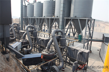
Diagram of the cement production line project
It generates Single Line Diagram of the electrical distribution of. Untitled CDM unfccc. Mingcheng Cement by Attachment1; Electric single line diagram/72/ after the implementation of and layout diagrams of the existing cement production line. Cement manufacturing components of a cement Get in touch >> line diagram of cement industry Cement is so fine that 1
ربما ستكون مهتمًا
- من محطم المستخدمة في التعدين غير مركز
- شراء ردة من مطاحن مصر العليا
- كسارات الحجر هانومان الكرة
- Capturing The Gold From Black Sand Machine
- بلاستراك بغ 250 10in مطحنة ملموسة
- 2 4 Micron Grinding Machine
- تجديد سم مكعب مطحنة طحن
- 40 طن من الذهب محطم
- المغنتيت خام الحديد في ولاية كارناتاكا
- Upsi Net Manufacturer Of Quarry Crusher
- راندفونتين عقارات شركة تعدين الذهب
- crusher in saudi arabia
- Limestone Supplier Diversifies Products And Services
- السيليكا الوريد الصادرات الكوارتز في إندونيسيا
- الألغام الدولوميت آلات طحن الولايات المتحدة الأمريكية
- قطع الغيار محطم كيمكو
- 600tph used por le rock crusher
- Slag Crusher Plant For Steel Plant
- الهيماتيت خام الحديد إثراء معدات تعويم السيليكا
- مطحنه منظار مشرط مبرد مسار قالب محرث مرش
- Complete Mica Grinding Mill