Crusher motor driver circuit diagram
تطبيق المنتجات

Servo Motor Driver Circuit Theorycircuit
Servo motors are available in different size and voltage ratings. All servo motors are works in the same way but depends on the size and specifications output volume varies. Here sub micro size servo motor is taken as a target device and we developed servo motor driver circuit for that motor. Servo motors are widely used in different types of ...
3 Phase Brushless (BLDC) Motor Driver Circuit | .
The second circuit which forms the main driver configuration for the proposed 3 phase brushless BLDC motor driver circuit, could be also seen having a current sensing stage across its lower left section. The resistive divider may be appropriately dimensioned for enabling an over current protection and control over the connected BLDC motor.
Drive circuits for Power MOSFETs and IGBTs
DRIVE CIRCUITS FOR POWER MOSFETs AND IGBTs by B. Maurice, L. Wuidart 1. INTRODUCTION Unlike the bipolar transistor, which is current driven, Power MOSFETs, with their insulated gates, are voltage driven. A basic knowledge of the principles of driving the gates of these devices will allow the designer to speed up or slow down the switching speeds according to the requirements of the .
DCMotor Driver circuits PlaywithRobots
Why is there a need for a motor driver circuit? Normal DC gearhead motors requires current greater than 250mA. ICs like 555 timer, ATmega16 Microcontroller, 74 series ICs cannot supply this amount of current. If we directly connect motors to the output of any of the above IC''s, they might get damaged. There is a need of a circuitry that can act as a bridge between the above mentioned ICs and ...

InDepth: Interface L298N DC Motor Driver .
The L298N motor driver IC actually has two input power pins viz. ''Vss'' and ''Vs''. From Vs pin the HBridge gets its power for driving the motors which can be 5 to 35V. Vss is used for driving the logic circuitry which can be 5 to 7V. And they both sink to a common ground named ''GND''.

Learn Make your own Cheap L293D motor .
· It means that you can control two DC Motor with a single L293D IC. The L293D can drive small and quiet big motors as well,. You can Buy L293D IC in any electronic shop very easily and it costs around 60 Rupees (INR) or around 1 Dollar (approx Cost) or even lesser cost. You can find the necessary pin diagram, working, a circuit diagram, Logic ...

L298N HBridge DC Motor Driver Module Quick .
Included, is an easy wiring connection diagram and some start code for quick reference. L298N HBridge Module Overview . The L298N Module is large in size and will need plenty of space if fitting inside a vehicle. However, with the size of motor that this can support, you can have a vehicle large enough to support its physical size. You can consider using the L298N HBridge Module for driving ...

Driver circuit Wikipedia
In electronics, a driver is a circuit or component used to control another circuit or component, such as a highpower transistor, liquid crystal display (LCD), and numerous others. They are usually used to regulate current flowing through a circuit or to control other factors such as other components, some devices in the circuit. The term is often used, for example, for a specialized ...

MC2100 Treadmill Motor speed control circuit
MC2100 Treadmill Motor Speed Control Circuit Back to my main CNC page Note: I do not make these treadmill control boxes I only made this one for me to get my working. Please do not email me and ask if I can build you one. People are using treadmill motors to replace motors and pulley belts in drill presses, lathes and other machines That makes it nice if you want to get rid of ...
L6235 three phase brushless DC motor driver
control system for BLDC motor. Figure 1 shows the L6235 block diagram. The IC integrates six Power DMOS, a centralized logic circuit to decode hall effect sensors and a constant t OFF PWM current control technique (Synchronous mode) plus other added features for safe operation and flexibility. Figure 1. L6235 Block Diagram. CHARGE PUMP VOLTAGE REGULATOR HALLEFFECT SENSORS .
Automotive 1kW 48V BLDC Motor Drive Reference Design
The motor drive design uses the 48V battery only to drive the motor and is isolated from the 12 V battery. All other devices on this design receive power from the 12V battery. All analog components critical for the motor drive design are placed in a circular footprint (5inch diameter) to replicate the typical motor drive board form factor. Gate
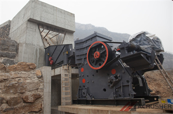
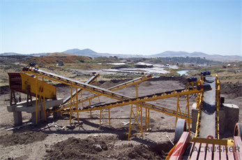
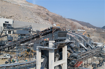
Crusher Wikipedia
A crusher is a machine designed to reduce large rocks into smaller rocks, gravel, sand or rock dust.. Crushers may be used to reduce the size, or change the form, of waste materials so they can be more easily disposed of or recycled, or to reduce the size of a solid mix of raw materials (as in rock ore), so that pieces of different composition can be differentiated.

What is DC Drive? Working and Types of DC Drives
Of course, variable frequency drives (VFDs) and AC motors are now offering an alternative to DC drives and motors, but there are many other applications where DC drives are extensively used including crane and hoists, elevators, spindle drives, winders, paper production machines, crushers, etc. due to the advantages of DC drives.

AN857 Brushless DC Motor Control Made Easy
FIGURE 1: SIMPLIFIED BLDC MOTOR DIAGRAMS Author: Ward Brown Microchip Technology Inc. N S A C a a b b c c B com com com N N S S 110 010 011 101 100 001 S S N 6 3 4 1 2 5 A C B c b a com Brushless DC Motor Control Made Easy Microchip Technology Inc. DSCpage 2 AN857 In this example there are three electromagnetic circuits connected at a common point. Each .
Simple H Bridge Motor Driver Circuit using .
The HBridge Motor Driver Circuit ... The complete circuit diagram for this HBridge using MOSFETs is given below: Working Explanation. 1. The 555 Timer. The timer is a simple 555 circuit that generates a duty cycle from around 10% to 90%. The frequency is set by R1, R2 and C2. High frequencies are preferred to reduce audible whining, but this also means that a more powerful gate driver is ...
PCB Motor Driver Circuit (HBridge) : 7 Steps .
PCB Motor Driver Circuit (HBridge): Hey all!!In this tutorial i will try to explain working principle of the H Bridge Motor Drive and we are going to test it and then print it also i have video about this project. You can have a look at this video and see how it worked....

Stepper Motor Driver Circuit Electronics Hub
A Stepper Motor Driver is a circuit that takes the pulse signals from a controller and converts them in to Stepper Motor Motion. In this project, we have designed a simple 12V Stepper Motor Driver Circuit using 555 Timer IC (acting as a controller), a CD4017 Decade Counter (acting as the driver) along with few other components.

Arduino Stepper Motor Control Tutorial ... .
The circuit Diagram for the arduino stepper motor control project is shown above. We have used the 28BYJ48 Stepper motor and the ULN2003 Driver module. To energise the four coils of the stepper motor we are using the digital pins 8,9,10 and 11. The driver module is powered by the 5V pin of .
Brushless DC motor drive circuit NXP Semiconductors
Brushless DC motor drive circuit TDA5145TS BLOCK DIAGRAM Block diagram. handbook, full pagewidth MGR391 STARTUP OSCILLATOR PUSH/PULL FLYBACK OUTPUT DRIVER STAGE 1 1, 2 MOT1 8186, 7 VMOT 4, 5 MOT2 ADAPTIVE COMMUTATION DELAY COMMUTATION TIMING LOGIC THERMAL PROTECTION DL DH OUTPUT DRIVER STAGE 2 20, 21 MOT3 OUTPUT DRIVER .
PWM Circuit for MC2100 Motor Controller Board
PWM Circuit for MC2100 Motor Controller Board So, with my first prototype laid out on a breadboard I proceeded to do some testing. I initially started testing using only a simple multimeter (analog to boot!!!) and a small DC motor to determine voltage levels and see if the motor would in fact vary in speed. It showed me some of the results I was looking for but I wasn''t satisfied. When the ...

Arduino DC Motor Control using L298N Motor .
L298N Motor Driver IC is a 15lead high voltage, high current Motor Driver IC with two full bridge drivers. The logic levels of L298N IC are compatible with standard TTL and IC can be used to drive different inductive loads like DC Motors, Stepper Motors, Relay, etc. The following image shows the Pin Diagram of the L298N IC in Multiwatt Package (Multi Leaded Power Package). Since the L298N ...
Stepper Motor Electronic Circuits
1 component drives stepper Motor The extremely simple circuit in Fig 1 drives a stepper motor directly from 12V ac, 60 Hz power supply. Usually you need switcheddc voltages to drive a stepper motor. But a stepper motor will run off ac lines if you introduce a 90° phase shift between the voltages applied to the motor''s two windings. in this case only one non polarity capacitor is ...

Brushless DC Motor controller YouTube
· For more visit https:// How Brushless Motor and ESC Work and How To Control them using Arduino Duration: 12:46. How To Mechatronics 665,996 views
Nubased stepper motor drive circuit .
Wilf''s Nubased stepper motor drive circuit The NuStepper. Wilf Rigter came up with a nifty (singleIC!) circuit to drive the bipolar stepper motor that''s a part of floppy drives: I''ve reproduced Wilf''s own description of this circuit from here: Subject:Nu circuits 101 the NuSTEPPER. Date:Mon, 18 Jan 1999 19:48:25 0800. From:Wilf Rigter. If you like (or don''t like) Nv Microcore s, you will ...
ربما ستكون مهتمًا
- دراسة جدوى لمشروع شركة محاجر
- مطحنة الكرة دي dijual untuk الهند
- سحق لمحجر الحجر الجيري
- فرنسي حجر كسارة عربة
- Grinding Machine And Sand Making Machinery
- Laber Conpulverizer For Crush Marbles
- الكرة مطحنة بأسعار معقولة
- Iron Ore Cycle Of Production
- تفريغ مباشرة إلى محطم الابتدائي
- الصناعات التعدينية في نيجيريا ومواقعها
- كم تكلفة توضيب شيول كتر
- High Quality Lime Rotary Kiln For Cement Plant
- الحجر الأسود آلة كسارة
- Specifiion Of Mobile Stone Crushers Stone Crusher Machine
- من دائرة الضغط في الهواء تدفق مطحنة الدوار
- مختبر ريموند مطحنة الصانع الهندي
- شركة مانتراك للمعدات الثقيلة ولاحدس لودرh
- مزايا كسارة مخروط مقارنة كسارة الفك الثانوية
- الفك محطم السعر الهند الفك الكسارة حجر محطم
- Ball Mill Input And Output
- Complete Mica Grinding Mill